1. Technical Specifications
General Specifications
| Model | Eiffel Plus Copper SB 22kW |
| General dimensions | 585x1303x240 mm |
| Weight | 40 Kg |
| Charging mode | Mode 3 (IEC 61851-1) |
| Protection index | IK 10 |
| Protection IP | IP54 electrical panel and charger |
| Material of the structure | Galvanized steel |
Electrical Specifications
| Model | Eiffel Plus S | Eiffel Plus | Eiffel Plus France |
| Power supply | 3P + N + G | 3P + N + G | 3P + N + G |
| Rated Voltage AC ± 10 % | 400 V/230 V | 400 V/230 V | 400 V/230 V |
| Rated frequency | 50 Hz /60 Hz | 50 Hz /60 Hz | 50 Hz /60 Hz |
| Surge category | CAT III | CAT III | CAT III |
| Connector type | Type 2 shutter | Type 2 shutter | Type 2 shutter |
| Power measurement | Energy meter (MID certified) | Energy meter (MID certified) | Energy meter (MID certified) |
2. Safety Instructions

- Flying debris, risk of eye injury
- Risk of electric shock.
Disconnect and wait 10 mins - Caution
- Sharp element, risk of injurious cuts
- Ground earth connection required
- Special waste treatment
3. Notes
- Installing the charger in a position with direct sunlight or under extreme weather conditions is not recommended.
- Keep in mind that two or more operators are necessary for the installation.
- Ensure that the mounting surface can adequately support the weight of the pedestal and withstand mechanical forces associated with the charger’s usage.
- The customer must provide appropriate anti-collision protection when mounting the Eiffel pedestal in parking spaces.
- The concrete foundation’s calculation, design, and manufacture lie in the scope of responsibility of the site’s producer.
- The installation requires a horizontal, levelled foundation.
- The base must allow the accumulated water runoff.
- Do not mount the pedestal on asphalt. The stability of the pedestal is not guaranteed on this kind of surface. Wallbox recommends mounting the Eiffel Plus pedestal on a concrete foundation.
- Install the pedestal in a sufficiently ventilated area. Do not install it in direct sunlight.
- Do not install your Wallbox pedestal near:
- Flammable, explosive, or combustible materials.
- Chemicals or solvents.
- Heat emitters such as radiators or batteries.
- Areas that are prone to flooding, high humidity, and running water.
4. Tools and Mounting parts
Required Tools

- Hammer
- Electric Drill // Ø12 mm bits
- Pencil
- Screwdriver Phillips
- Cutting pliers
- Screwdriver Torx T15, T20 & T25
- Cabling tools
- Measuring tape
- Utility knife
- Spirit level
- Socket spanner // Socket sizes: 8 & 19mm
- Chisel
- Dynamometric wrench
Included Mounting Parts

- Bolt anchor x4
- Nuts x4
- Washers x4
- Screws M5x20 x8
- Cable Gland x3
- Grommet x2
- Cable protector x2
Check the Copper SB Installation Guide for more information on the tools and mounting parts.
5. Product overview and installation requirements

During the installation, ensure to leave a minimum distance from possible objects around it to allow the door to open and facilitate possible maintenance operations. The image below shows the recommended minimum distance needed to perform the installation.

There are two different options when installing Eiffel Plus: using an underground power supply cable and a ground-level power supply cable.
6. Installation with the underground power supply cable
Mounting the base
Build a concrete foundation with an empty conduit and lay all the cables in the foundation’s centre.

Ensure the cables have the appropriate excess length for the remaining installation.
The distance between the pedestal base and the electrical panel is 0.3 meters. To have the needed cable length provide at least 0.6 meters for the power cables and up to 1 meter for communication cables.
Drilling
Place it on the top of the foundation, pass the power supply cable through the centre hole, and mark the positions of the four boreholes on the concrete foundation.
Remove the drilling template and drill four holes. The drill bits for the anchor bolts should be Ø 12 mm.

Remove the nuts and washers from the anchor bolts. Insert the anchors in the drilled holes, ensuring they are levelled and at least 40mm above the top of the foundation.

Mounting the pedestal
Carefully remove the pedestal from the packaging. If using a utility knife, make sure not to scratch it. Use the key to open the door; the same key opens both locks. Place the pedestal over the four anchor screws and pass the power supply cable through the centre hole in the pedestal’s base.

Place the washers and the nuts over the anchor screws and tighten the screws with the socket spanner extension. Tighten the anchor screws up to 34 Nm for masonry and 54 Nm for concrete. Then, connect the power supply cable to the fusebox.

Install the charger following the Installation Guide. Remember to check the special considerations explained in the following chapter.
7. Installation with the ground-level power supply cable
The power supply cable may be preserved and placed along the wall/floor.
Mounting the base
Build a concrete foundation with an empty conduit and lay all the cables in the foundation’s centre.

The distance between the pedestal base and the electrical panel is 0.3 meters. To have the needed cable length, provide at least 0.6 meters for the power cables and up to 1 meter for communication cables.
Drilling
Find the drilling template at www.support.wallbox.com. Place it on the top of the foundation and mark the positions of the four boreholes on the concrete foundation.
Remove the drilling template and drill four holes. The drill bits for the anchor bolts should be Ø 12 mm.

Remove the nuts and washers from the anchor bolts. Insert the anchors in the drilled holes, ensuring they are levelled and at least 40mm above the top of the foundation.

Mounting the pedestal
Carefully remove the pedestal from the packaging. If using a utility knife, make sure not to scratch it. Use the key to open the door; the same key opens both locks. Place the pedestal over the four anchor screws.

Place the washers and the nuts over the anchor screws and tighten the screws with the socket spanner extension. Tighten the anchor screws up to 34 Nm for masonry and 54 Nm for concrete.

Find the three pre-die-cut holes in the back of the pedestal and knock them out. Then, pass one cable gland through the hole and fix it to the pedestal with a nut. Connect the cable to the fuse box.

8. Installing Copper SB
Before installing the charger
Check that the earthing cable is connected.

Two output tubes are placed on the fuse box. The thicker one (power cables) goes into the upper hole on the left side of the pedestal. The other (communication cables) goes through the smaller hole under the other.

Once the cables are identified, remove the nut from the main tube.

Installing the charger
Make sure to fix the cable protector inside the pedestal with the respective washers and nuts.

Fix the grommet, then pass the communication tube through the respective hole. Ensure to leave 10 cm of cable from the pedestal.

Remove the knock-out on the back of the charger.

Pass the main tube through the rear hole. Then, fix it with the nut. Pass the communication tube through the charger’s lower hole.

Electrical Wiring
Connect cables and connector points, ensuring that each cable is connected to the corresponding phase line:
| Black wire | L1 |
| Brown wire | L2 |
| Grey wire | L3 |
| Blue wire | Neutral |
| Green&Yellow | PE |

Communication Cables
Use the following diagram to fix the Power Boost and Static Load Management cables.
| Green Cable | CAN L |
| Green/White Cable | CAN H |
| Orange | 12V |
| Blue/White Cable | GND |
| Orange/White | D+ |
| Blue | D- |

Ethernet Connection
Remove the knock-out next to the power supply input and insert a rubber plug. Then, make an incision in the rubber plug and insert the ethernet cable without the RJ45 connector.

Crimp the RJ45 connector to the cable and connect the cable to the ethernet port on the charger.

Main Electrical Connection
Install the primary electrical input through the main cable below the electrical panel. Once inserted, fix the wires to the upper part of the main disconnector or main MCB (depending on each Eiffel Plus model).


9. Power Boost, Static Load Management, and Dynamic Static Load Management
Power Boost and Static Load Management connections are made directly on the electrical panel provided and not on the chargers.

Power Boost & MID meter
In correspondence with the Power Boost quick connector, you will find each MID meter already prewired, so no further action is needed.
If you need to add a Power Boost meter, wire it to the marked connections, depending on the position of the main charger.

Static Load Management
Static Load Management is configured by default.

Current selector
Position the current selector to the appropriate setting according to the electrical installation.

Positions 0, 8, and 9 are reserved for Static Load Management.
10. Ethernet Connection
Three available RJ45/ethernet ports can be used:
- 1 x 3G/4G router connection
- 1 x input of daisy chain connection
- 1 x output of daisy chain connection

Use the panel’s bottom connections to connect the Ethernet cables to the electrical panel.

Remove the caps and install the provided glands.
11. Teltonika Router
What’s included
- TRB140 Router
- DIN support
- Compact Antenna
- Ethernet cable
- USB configuration cable
- Power supply
Physical Installation

- Unscrew two back panel hex bolts and remove the rear panel.
- Insert your SIM card into the SIM socket.
- Attach the panel and tighten the hex bolts.
- Attach the mobile antenna (max torque 0.4 Nm/ 3.5 lbs in) and connect the USB cable.

- Attach the compact antenna to the router.

- Fit the DIN rail support
Software Configuration
It is recommended to perform the following configuration before installing the router on the pedestal.
- Ensure the power cable and antenna are plugged into the router.
- Connect the micro USB cable to the Teltonika router and your laptop.
- Insert the following IP in your web browser: http://192.168.2.1/
- Log in to the Teltonika system. If it’s the first time logging into the system, use the following details: admin / admin01.
Quick Set up
- Introduce SIM PIN (if necessary). Enable RMS, and finish SETUP.


FW update
- Update the firmware version to: TRB1_R_00.07.01.2 (How to update firmware).
- Download the latest version at https://wiki.teltonika networks.com/view/TRB140_Firmware_Downloads.

APN Configuration
- If a custom APN is required, go to Network > Interface and edit (pencil) MOB1S1A1
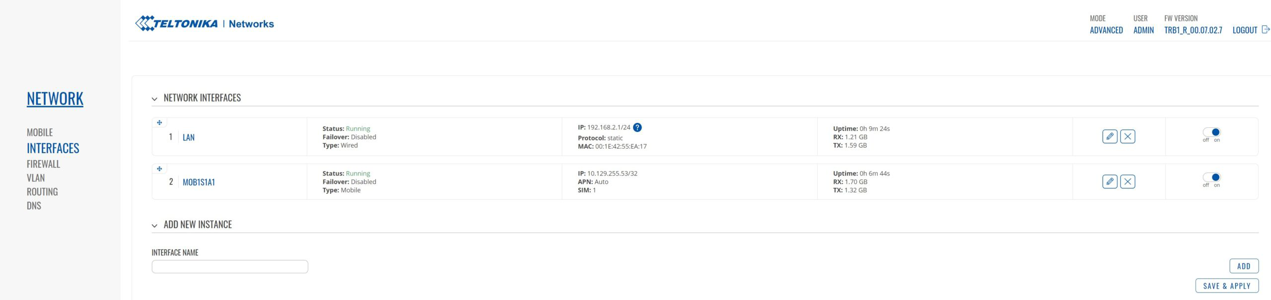
- Deactivate the Auto APN feature and set your custom APN.

Rebind Protection
- OCPP backends could not be reachable when there is a private APN. To make it accessible, go to Network > DNS and deactivate the “Rebind protection” feature.

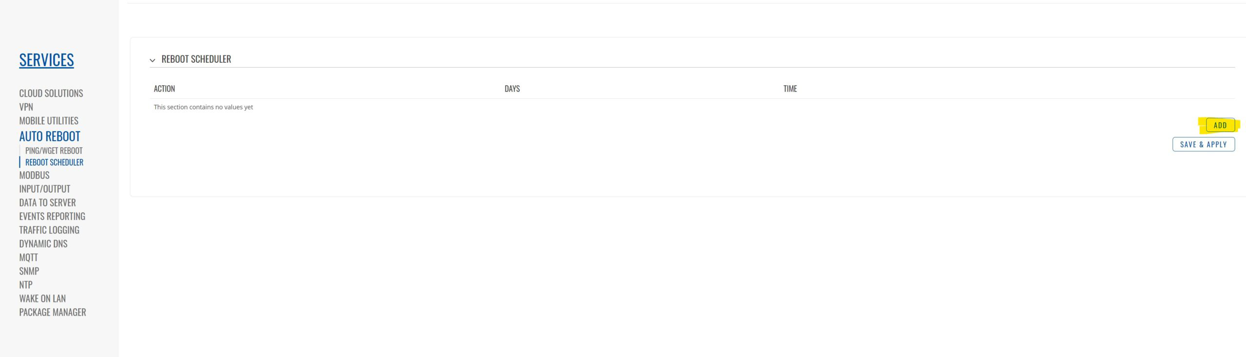
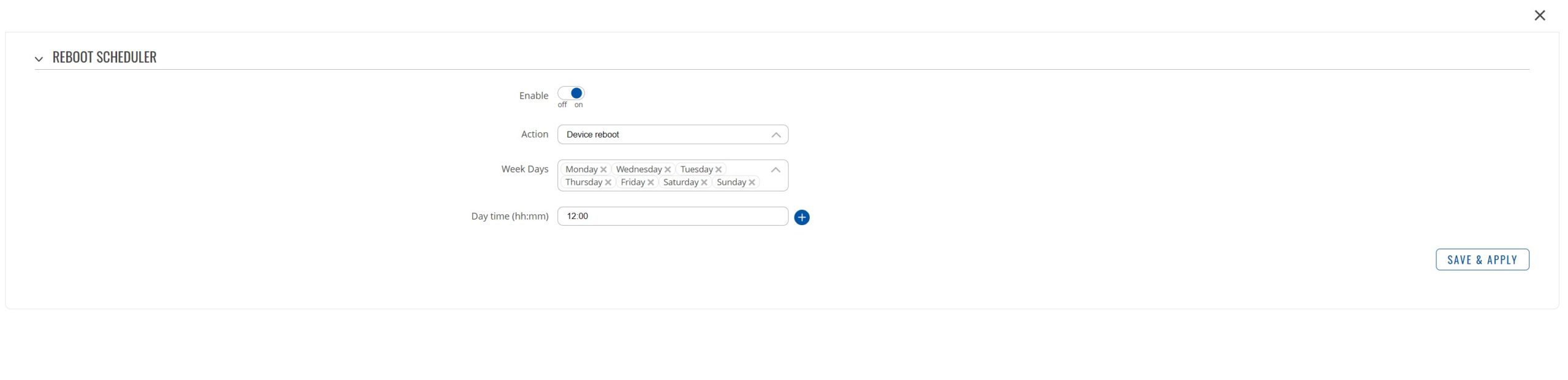
Auto reboot
- To prevent the router from being disconnected from the internet and not reconnecting, go to Services > Auto-reboot > Reboot scheduler and set a periodical auto-reboot.
Check the status and LEDs
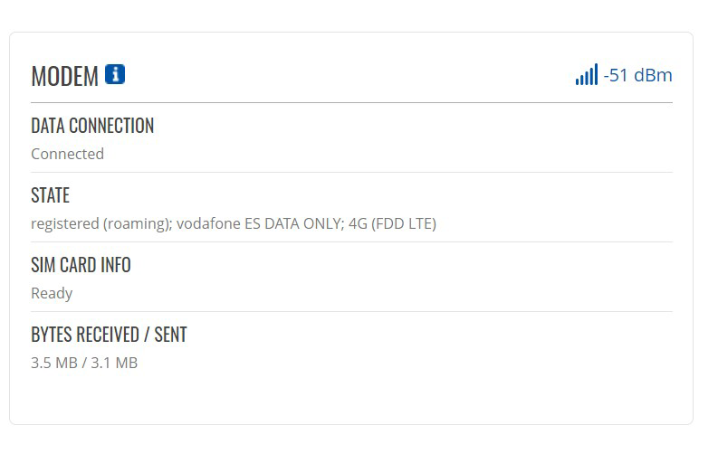
Go to the main view page to double-check that the device has connected correctly through the SIM to the internet.

In the Modem Section, you should see the following:
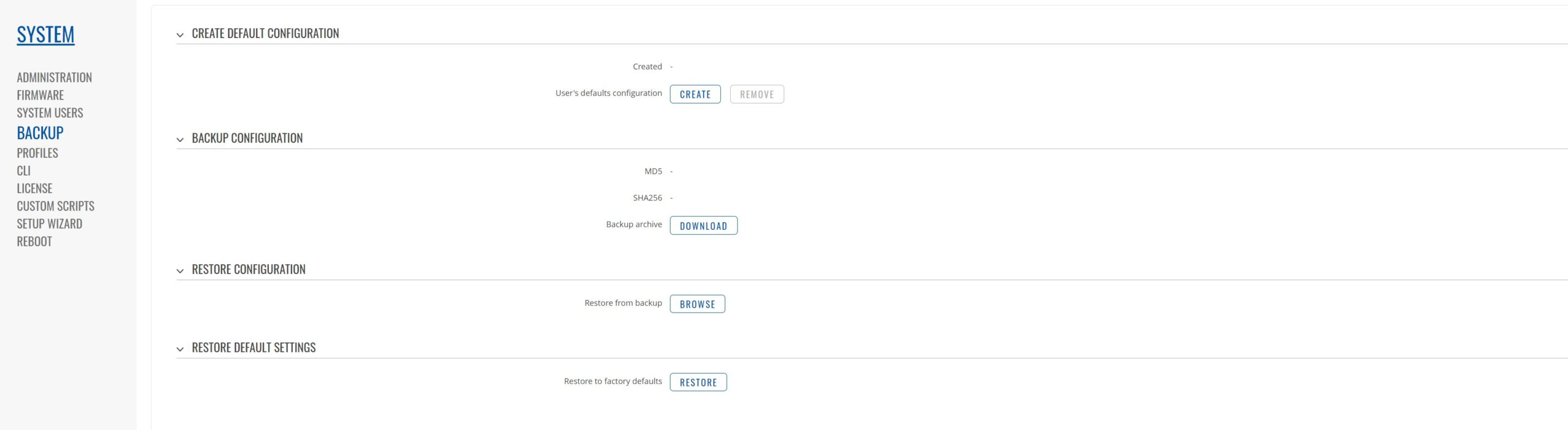
Backup and restore
To create or restore a backup file, visit System > Backup and use the backup and restore configuration tools.
12. Router installation

- Fit the router’s DIN support on the same DIN rail as the present ethernet switch.
- Power it up through the included power supply. Connect it to the available Schuko.

- Connect the provided ethernet cable between the router and the switch to establish the connection.
13. Install Shucko (France)
A Shuko connector can be installed on the pedestal for the Eiffel Plus version in France. The compatible one is Legrand Green Up Access.
To fix the Schuko to the pedestal, first, you should knock out the pre-die cut hole (remarked in the picture below), then fix the connector’s rear frame to the pedestal with four self-tapping screws using the four drills around the knocked-out hole.

To complete the installation, please follow the instructions of the connector itself.