Table of Contents
1. Datasheets
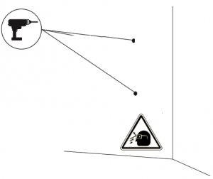
2. Safety Warnings

-
- Flying debris, risk of eye injury
- Risk of electric shock. Disconnect and wait 10 mins.
- Caution
- Sharp element, risk of dangerous cuts
- Ground earth connection required
- Special waste treatment
3. Safety Instructions
You can consult the Safety Instructions here.
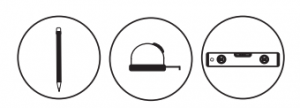
4. Tools
Required tools

-
- Hammer
- Step drill bit 32mm and bit 8mm
- Pencil
- Flat Screwdriver
- Pillips Screwdriver
- Cutting Pliers
- Security Torx T20 and HEX tube key ⌀6
- Measuring Tape
- Utility Knife
- Spirit Level
- A smartphone (not pictured here)
5. Socket Versions
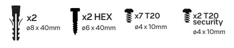
Included mounting parts
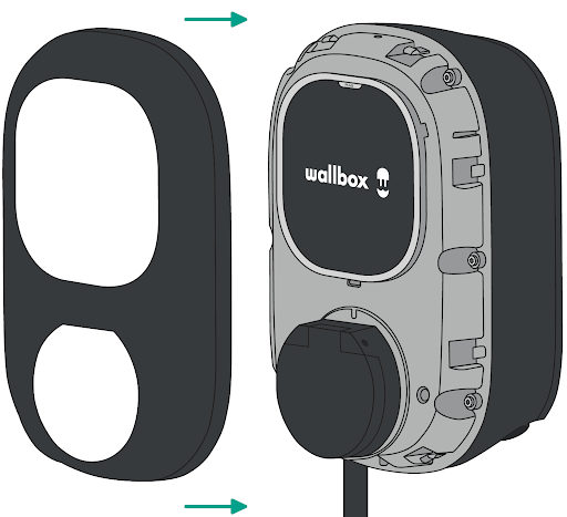
5.1 Installing the Wall Plate
-
- Remove the tape from the wall plate (257.5mm x 188mm) to detach it from the charger.
-
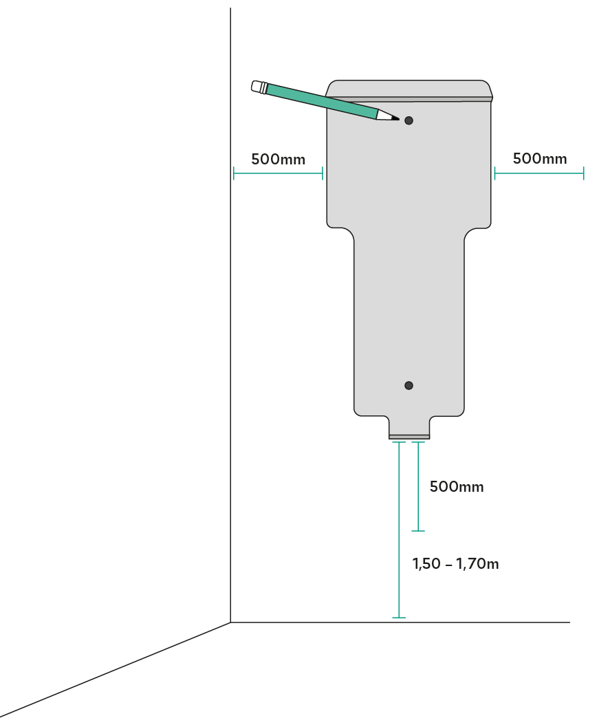
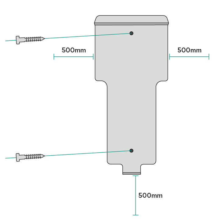
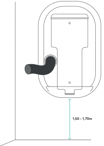
- Place the wall plate straight. Use a pencil, a measuring tape and a sprit level to mark the position of the screws. Maintaining a minimum clearance of 500mm on both sides of the wall box is recommended for optimal installation.
- Place the wall plate straight. Use a pencil, a measuring tape and a sprit level to mark the position of the screws. Maintaining a minimum clearance of 500mm on both sides of the wall box is recommended for optimal installation.
-
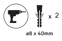
- Drill two holes with the appropriate-sized bit. Align the wall plate with the holes. If you mount your charger on a solid wall, use the wall anchors provided.
-
- Drill two holes with the appropriate sized bit. Place the wall plate in alignment with the holes. If you mount your charger on a solid wall, use the wall anchors provided.
- Drill two holes with the appropriate sized bit. Place the wall plate in alignment with the holes. If you mount your charger on a solid wall, use the wall anchors provided.
-
- Firmly mount the wall plate using the provided wall screws. Do not over-tighten the screws. If the power supply wiring comes from the wall, place the wires through the hole before fixing the wall plate.
- Firmly mount the wall plate using the provided wall screws. Do not over-tighten the screws. If the power supply wiring comes from the wall, place the wires through the hole before fixing the wall plate.
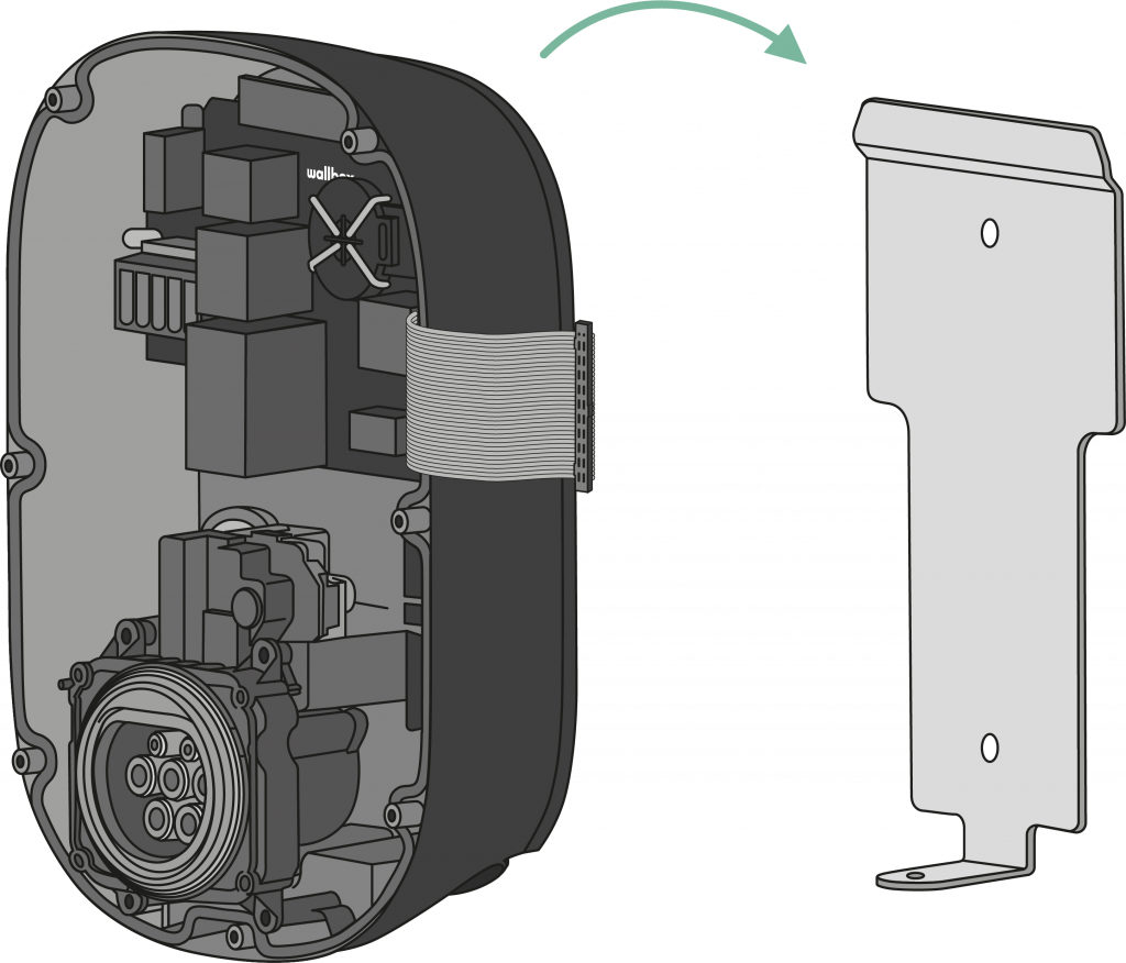
5.2 Preparing the Charger
A qualified specialist electrical contractor must carry out the entire installation of the Wallbox charger.
-
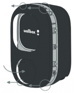
- Unclip the style cover carefully by pressing the socket lid with your fingers.
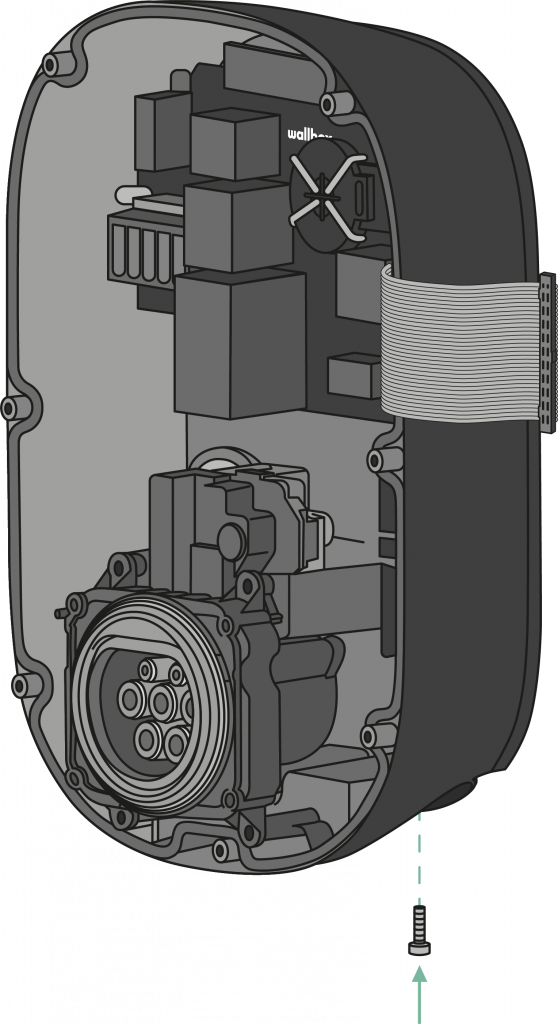
-
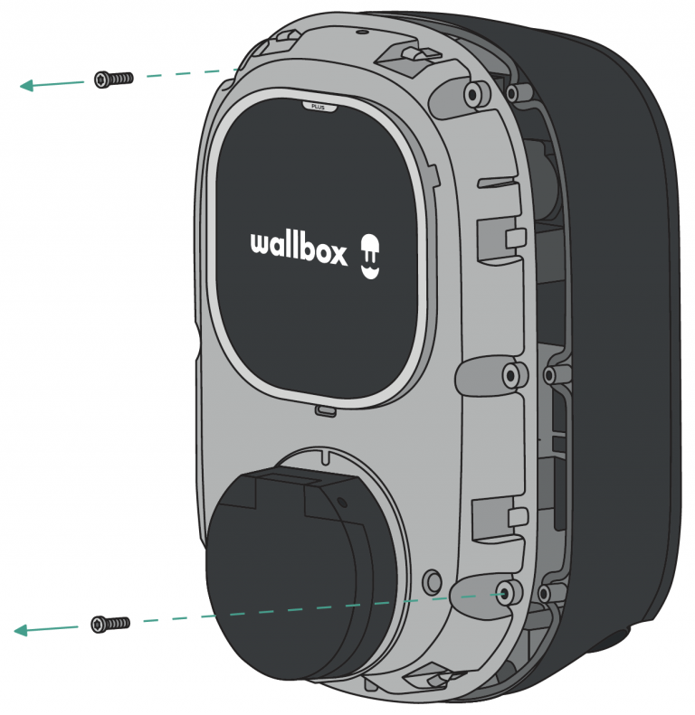
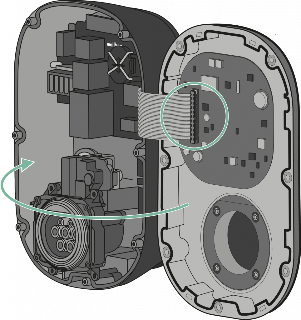
- Remove the two corner screws and carefully lift the cover.
-
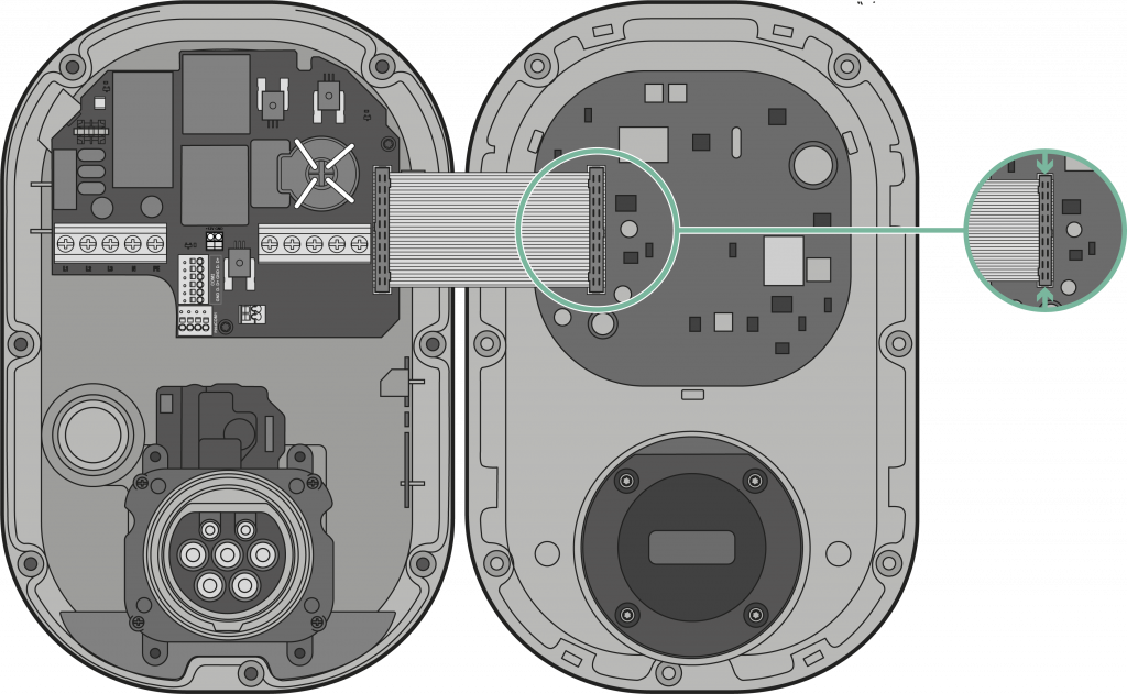
- Carefully detach the ribbon cable from the cover by pressing the lateral latches. Set the cover aside.
5.3 Lower Connection
-
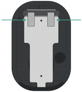
- Lift your charger and hang it from the top of the wall plate.
-
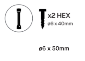
- Secure the charger to the wall plate using the security screws.
- Secure the charger to the wall plate using the security screws.
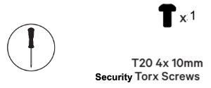
-
- Make an incision on the lower grommet and insert the power supply cable. Make sure the grommet seals the power cable supply insertion entirely.
- This cable should also be inserted on the lower grommet if an Ethernet connection is needed. See details in section 5.6.

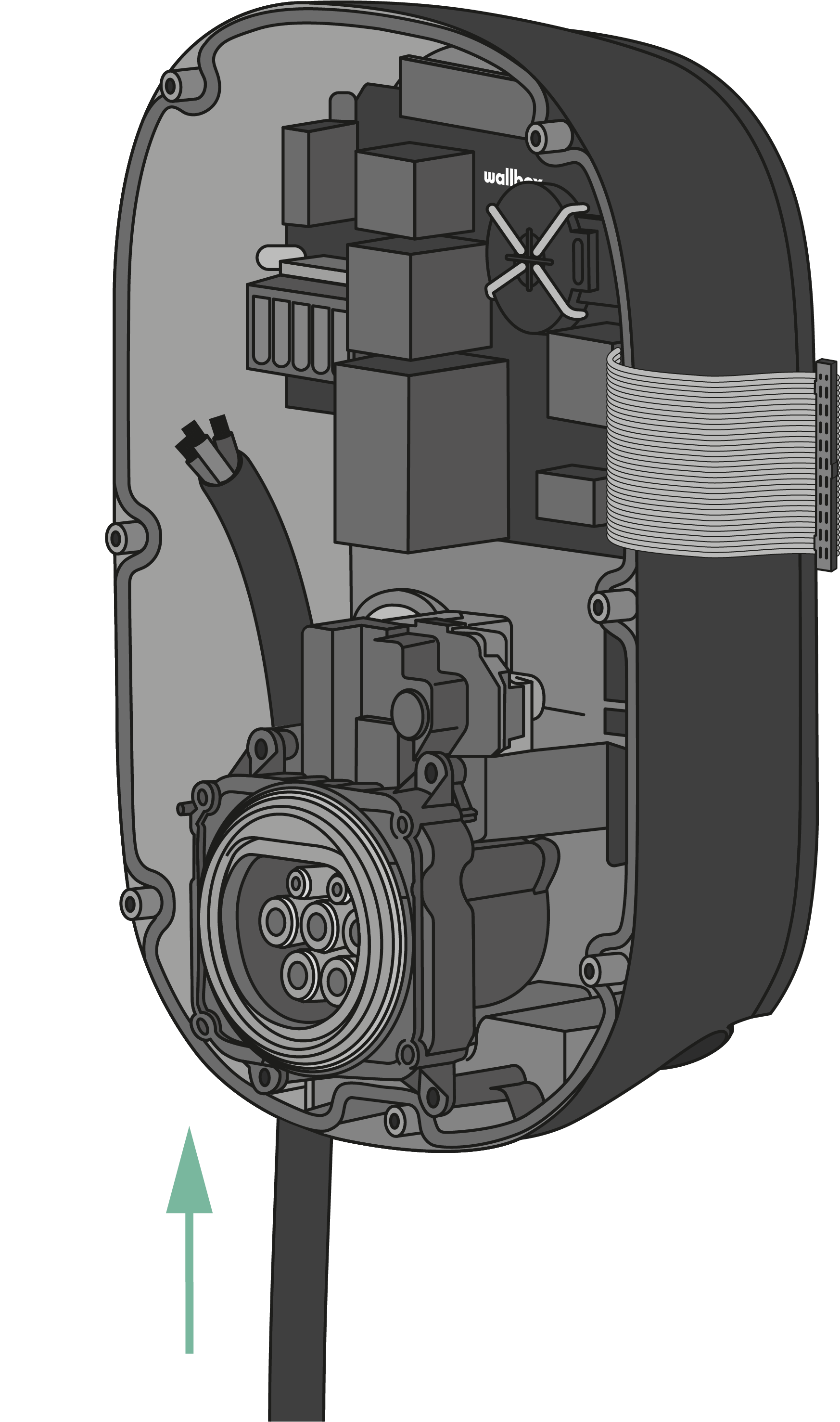
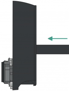
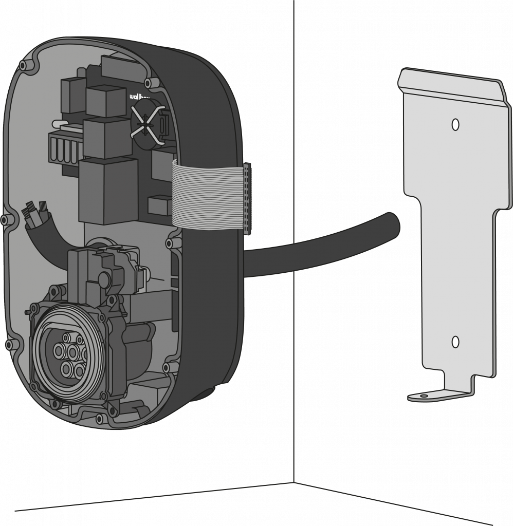
5.4 Rear Connection
-
- Make an incision on the rear grommet and insert the power supply cable. Make sure the grommet seals the power cable supply insertion entirely.
- If Ethernet is needed, this cable should also be inserted into the rear grommet. Please refer to the section 5.6
-
- Lift your charger and hang it from the top of the wall plate.
-
- Secure the charger to the wall plate using the security screws.
- Secure the charger to the wall plate using the security screws.

-
- Proceed to the next section to connect the power supply cable.
5.5 Electrical Wiring
Please refer to the wiring diagram provided below for your electrical setup.
Single Phase Version

-
- Single Phase Set-up
- Bi-phase No Neutral
- Single Phase PME
Three Phase Version

D. Three Phase Set-up
E. Three-phase No Neutral
F. Bi-phase Set-up
Check compatible EV models supporting this configuration for the Three-phase, no-neutral installation.
Ensure the maximum voltage is less than 264V between L & N inputs.
5.6. Ethernet Connection (Pulsar Pro only)
-
- Locate the Ethernet connector inside the charger.

-
- Connect the Ethernet Cable and ensure it is connected to the router on the other end.
5.7. Maximum Current Selection
-
- Locate the current selector inside the charger.
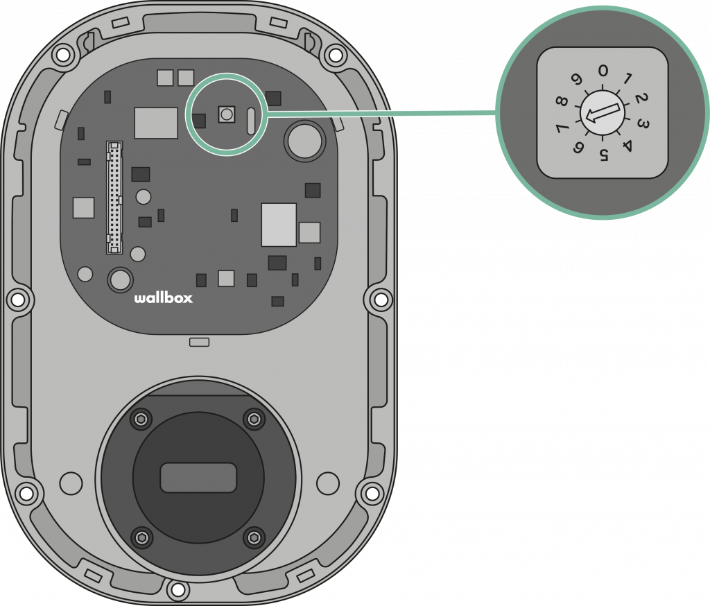
-
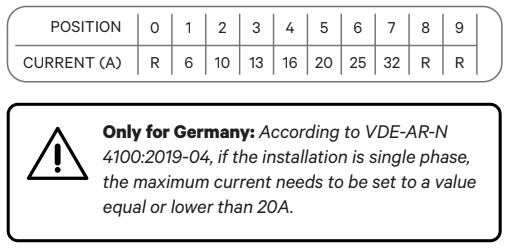
- To set the charger’s maximum charging current, position the current selector to the appropriate setting following the tab. Make sure the selector does not point to 0, 8, or 9.
Connection of a control cable per EnWG §14 A (Germany Only)
The Pulsar Pro and Pulsar Max are prepared for the connection of an external control cable via a terminal block, which the local energy supplier can use to reduce its charging power to 6 A (4.2 kW) if required.
The following requirements apply to the control cable:
-
- Solid conductor, 0.5 to 1.5 mm², stripping length:
-
- 9 mm x Fine-stranded conductor, 0.5 to 1.5 mm² / 0.5 to 1.0 mm² with ferrules, stripping length: 9 mm
To connect, proceed as follows:
-
- Open the centre grommet with the pick tool.
- Insert the two-core control cable into the housing.
- Connect the control cable to the terminal labelled +12V GND on the main circuit board of the wall box.
6. Tethered Versions
Included mounting parts

-
- Phillips Screws ø6 x 50 mm
- Phillips Screws ø5 x 40 mm
- Wall Anchors ø8 x 40 mm
- M32 Grommet
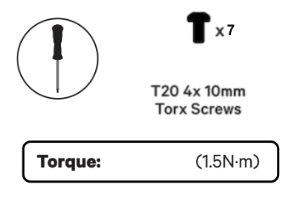
- Torx Screws T20 4 x 10 mm
- Torx Screws T15 ø3.5 x 8 mm
6. 1. Preparing the Charger
-
- Remove the two corner screws and carefully lift the cover. Then, carefully detach the ribbon cable to set the cover aside.

6. 2. Installing the Wall Plate
-
- Remove the tape from the wall plate to detach it from the charger.
- Then, place it straight and mark three holes with a pencil.
- Now drill with an appropriate-sized bit and place the wall plate in alignment with the holes.

-
- Fix the wall plate to the wall, ensuring not to over-tighten the screws. If you are mounting your charger on a solid wall, use the wall anchors provided with your charger.

-
- If the power supply wiring comes from the wall, place the wires through the hole before fixing the wall plate.

6. 3. Lower Connection
-
- Lift your charger and hang it from the top of the wall plate. Secure the charger to the wall plate with the appropriate screws, avoiding over-tighten.
- Make an incision on the grommet and insert the power supply cable.


6. 4. Rear Connection
-
- Using a 32-mm step drill bit, make a hole on the back of the charger. Then, make an incision in the grommet and insert the power supply cable.

-
- Fix your charger to the wall plate and then fix it using the appropriate screws.

6. 5. Electrical Wiring
Single Phase Version
-
- Single Phase Set-up
- Bi-phase No Neutral
- Single Phase PME
Three Phase Version
D. Three Phase Set-up
E. Three-phase No Neutral
F. Bi-phase Set-up
Check compatible EV models supporting this configuration for the Three-phase, no-neutral installation.
Ensure the maximum voltage is less than 264V between L & N inputs.
6. 6. Maximum Current Selection
-
- Locate the current selector inside the charger.

-
- Position the current selector to the appropriate setting following the tab to set the charger’s maximum charging current. Ensure the selector does not point to 0, 8, or 9.
7. Configuring the Energy Management Solutions
-
- Consult the EMS Installation Guide to configure any Energy Management Solutions compatible with the Pulsar Plus Socket.
- Once installed, follow the activation instructions of each solution you previously configured: Solar Charging, Static Load Management, Dynamic Static Load Management.
8. Closing the Charger (Socket version)
-
- Carefully reattach the communication cable to the charger cover and close it.
-
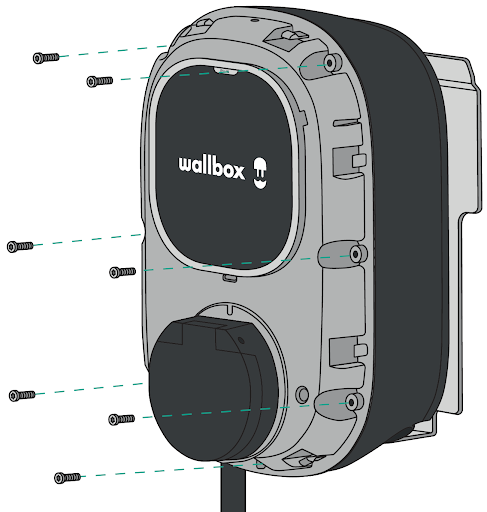
- Insert seven corner screws to secure the charger cover. Do not over-tighten.
-
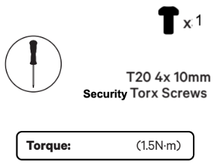
- Clip back the cover frame on the charger and fix it with the other security screw. Do not over-tighten.
9. Closing the Charger (Tethered versions)
-
- Carefully reattach the communication cable to your charger cover and close it.
- Insert the four corner screws to secure your charger cover. Make sure to properly align the bottom screw opening, place the cover frame on your charger, and attach the frame with the screw. Do not over-tighten.

10. Installing Accessories
10.1 Plug Holder
-
- Place the plug holder on the wall and mark the fixing points. Then, drill holes where the fixing points are marked.

-
- Insert the anchor screws into the fixing holes. Then secure the device to the walls by inserting and tightening the screws.
10.2 Accessories for Optimal Operation Under Direct Sunlight
While we recommend avoiding direct sunlight for optimal charger performance, we understand that specific installations may require this setup. To address this, we’ve developed the Sun Cover and Fan Module Kit to enhance charging speed and overall performance in sunny conditions.
-
- Compatibility: The kit is compatible with both Pulsar Max and Pulsar Pro models.
-
- Installation Made Easy: Each product includes QR codes linked to detailed installation guides for the fan module and sun cover, ensuring seamless installation by a certified installer.
-
- Ordering and Installation: The kit can be ordered under a specific item code and is designed to be easily retrofitted in the field by a certified professional.
Performance Recommendations To maintain optimal performance and safety
-
- Avoid installing chargers in direct sunlight whenever possible.
-
- Install chargers in well-ventilated areas to regulate temperature and ensure safe operation.
-
- Note that our chargers are certified to operate at temperatures up to 50°C, with performance adjustments (derating) applied above 40°C.
-
- The Sun Cover and Fan Module Kit can improve your charger’s reliability and performance, even in challenging sunlight conditions.
11. Making the charger smart
-
- Download the Wallbox app and create an account for the client.
- Follow this guide to add the charger to your newly created account.
- Make sure your charger is updated to its latest software version.
- You can now use all the charger smart features, such as scheduled charging sessions, managing the charger through the Wallbox portal and adjusting your charger settings.