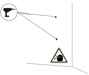
- A. Flying debris, risk of eye injury
- B. Risk of electric shock. Disconnect and wait 10 mins.
- C. Caution
- D. Sharp element, risk of dangerous cuts
- E. Ground earth connection required
- F. Special waste treatment
Required tools

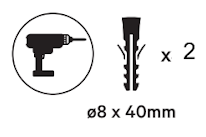
- Hammer
- Step drill bit 8mm
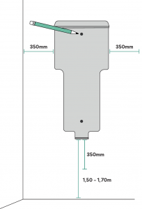
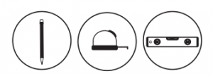
- Pencil
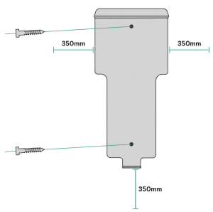
- Sprit Level
- Measuring Tape

- Cutting Pliers
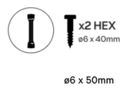
- HEX tube key ⌀6
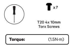
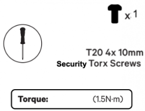
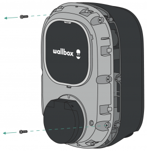
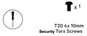
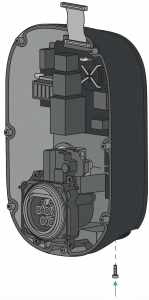
- Security Torx T20
- Utility knife
- Mobile Phone
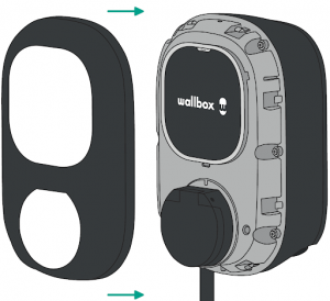
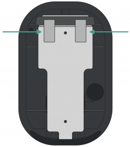
Included Parts


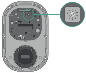
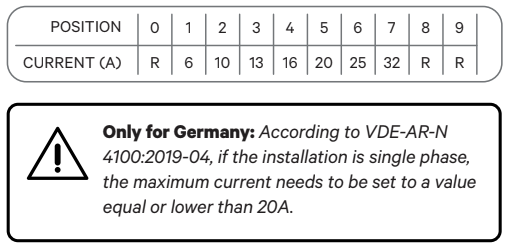
Please refer to the wiring diagram provided below following your electrical setup.