Installing an MID Meter with your Wallbox charger allows for precise and MID-compliant energy consumption measurement, essential for billing and regulatory purposes. This guide provides detailed steps for installing and configuring an MID Meter.
What is an MID Meter?
An MID (Measuring Instruments Directive) Meter is a certified power meter that records the energy consumption of your Wallbox charger installation with high accuracy. Complying with the MID standard, it provides precise energy readings, ensuring that you can use this data for billing or reimbursement purposes.
1. Before Starting: MID Meter and Installation Requirements
Wallbox supports two types of MID-certified power meters, which can be purchased from our online shop:
- Three-phase MID power meter: Suitable for three-phase installations (up to 65A).
- Single-phase MID power meter: Suitable for single-phase installations (up to 100A).
We recommend using an STP Cat 5E cable to perform the installation.
Before you begin, download the Wallbox App, create an account and add your charger to complete the configuration.
2. Installing the MID meter
Electrical wiring
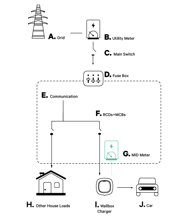
The MID Meter should always be installed after the Residual Current Devices (RCDs) and Miniature Circuit Breakers (MCBs) on the charger’s power line. This is represented as position F on the installation diagram.
Communication installation methods
Depending on the layout of your charging infrastructure, you can choose one of the following communication installation schemes:
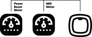
- Bus line installation: Recommended when the Power Boost (PB) and MID Meters are close together. Only one cable is needed to create the bus communication, wired to the RS485 connector.
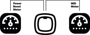
- Two lines installation: Used when PB and MID Meters are far apart. Two different connection lines are created, both connecting to the same point on the RS485 charger connector.
The following sections provide step-by-step instructions for three-phase and single-phase MID meter installations.
A. 3-phase MID meter installation
Refer to the installation guide provided with your MID power meter for additional details. Below are the key steps:
- Connecting the Charger to the Meter: Connect the MID Meter to your charger using an STP Cat 5E cable.
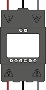
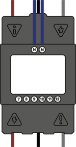
- Wiring the Power Meter:
- Connect the three phases (positions 1-2-3 for power input, 4-5-6 for power output).
- Ensure the phases are securely anchored. Install the insulation plate on top of the screws.
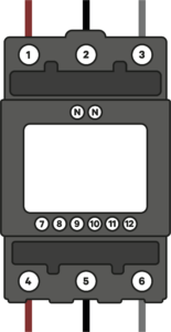
- Install the neutral. If larger cable cross-sections are used, downsize the neutral to fit the power meter.
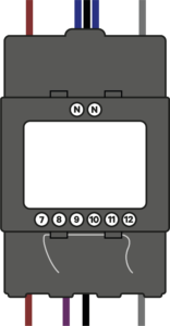
- Install the STP communication cable according to the diagram provided in your installation guide.
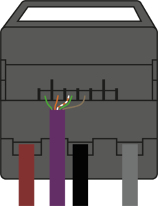
- Install the cable covers to secure your installation. If required, seal the covers with cables according to the local regulations.
- Wiring the Charger: Follow the instructions provided in your charger’s installation guide.
- Termination Resistance Activation:
- For Bus Line Installation: Set the charger’s RS485 switch to the “T” position. Only the Power Boost meter needs termination resistance.

- For Two Lines Installation: Set the RS485 switch to the “NT” position and wire the termination resistance bridge to both MID and PB meters.

- Current Selector Configuration: Once the MID Meter is installed, configure it through the Wallbox App (instructions in the next section).
B. Single-phase MID meter installation
For further assistance, refer to the installation guide included with your MID Meter model.
- Connecting the Charger to the Meter: Connect the MID Meter to the charger using an STP Cat 5E cable.
- Wiring the MID Power Meter:
- Install the MID power meter on the DIN rail.
- Install the STP communication cable as shown in the diagram.
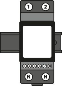
- Connect the phase and neutral wires. Ensure they are securely anchored, then install the insulation plate over the screws.
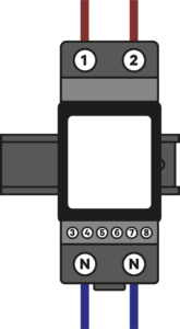
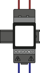
- Install the STP communication cable as shown in the diagram.
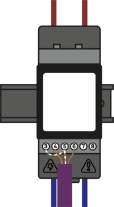
- Install the last cable cover to secure your installation. Seal the covers with the cables as required by local regulations.
- Wiring the Charger: Follow the instructions in your charger’s installation guide.
- Termination Resistance Activation:
Pulsar Plus, Commander 2 and Copper SB have two different termination resistances. The one devoted to MID and PB meters is marked as “RS485”.
- For Bus Line Installation: Set the charger’s RS485 switch to the “T” position. Only the Power Boost meter needs termination resistance.

- For Two Lines Installation: Set the RS485 switch to the “NT” position and wire the termination resistance bridge to both MID and PB meters.

- Current Selector Configuration: The MID Meter is installed correctly. Proceed to configure it via the Wallbox App as explained below.
4. Configuring the MID Meter Through the Wallbox App
To complete the setup and start using your MID Meter for accurate energy measurement, follow these steps in the Wallbox App:
- Download and Open the Wallbox App: Ensure you have the latest version of the app from the Play Store or App Store.
- Log in to Your Account: Enter your credentials to log in, or register for a new account if you don’t have one.
- Select Your Charger: Choose the charger that has the MID Meter installed from the list and connect to it via Bluetooth.
- Go to Charger Settings:
- Navigate to Settings > Energy Features > MID current measurement.
- Activate MID Current Measurement: Toggle on the “MID current measurement” option.
- Enter the MID Meter Serial Number:
- Tap on the arrow next to the “MID Meter” entry.
- Enter the last six digits of the MID Meter’s serial number (found on the sticker below the MID Meter’s display). If the serial number does not match, it won’t be configured.
- Set Auto-Stop Parameters:
- Define a switch-off limit for charging if the MID connection is lost. Choose between energy (kWh) or time (minutes) for auto-stop configuration.
- Default values:
- kWh: 1 kWh (Max: 22 kWh)
- Time: 1 minute (Max: 60 minutes)
- Save Settings: Confirm and save your settings. Your MID Meter is now properly configured.
- Verify Configuration: Visit the Wallbox portal at my.wallbox.com/login to check if your MID Meter is configured correctly. The MID Meter icon should appear next to your charger’s name if everything is set up correctly.
What is an MID Meter?
An MID (Measuring Instruments Directive) Meter is a certified power meter that records the energy consumption of your Wallbox charger installation with high accuracy. Complying with the MID standard, it provides precise energy readings, ensuring that you can use this data for billing or reimbursement purposes.
1. Before Starting: MID Meter and Installation Requirements
Wallbox supports two types of MID-certified power meters, which can be purchased from our online shop:
- Three-phase MID power meter: Suitable for three-phase installations (up to 65A).
- Single-phase MID power meter: Suitable for single-phase installations (up to 100A).
We recommend using an STP Cat 5E cable to perform the installation.
Before you begin, download the Wallbox App, create an account and add your charger to complete the configuration.
2. Installing the MID meter
Electrical wiring
The MID Meter should always be installed after the Residual Current Devices (RCDs) and Miniature Circuit Breakers (MCBs) on the charger’s power line. This is represented as position F on the installation diagram.
Communication installation methods
Depending on the layout of your charging infrastructure, you can choose one of the following communication installation schemes:
- Bus line installation: Recommended when the Power Boost (PB) and MID Meters are close together. Only one cable is needed to create the bus communication, wired to the RS485 connector.
- Two lines installation: Used when PB and MID Meters are far apart. Two different connection lines are created, both connecting to the same point on the RS485 charger connector.
The following sections provide step-by-step instructions for three-phase and single-phase MID meter installations.
A. 3-phase MID meter installation
Refer to the installation guide provided with your MID power meter for additional details. Below are the key steps:
- Connecting the Charger to the Meter: Connect the MID Meter to your charger using an STP Cat 5E cable.
- Wiring the Power Meter:
- Connect the three phases (positions 1-2-3 for power input, 4-5-6 for power output).
- Ensure the phases are securely anchored. Install the insulation plate on top of the screws.
- Install the neutral. If larger cable cross-sections are used, downsize the neutral to fit the power meter.
- Install the STP communication cable according to the diagram provided in your installation guide.
- Install the cable covers to secure your installation. If required, seal the covers with cables according to the local regulations.
- Wiring the Charger: Follow the instructions provided in your charger’s installation guide.
- Termination Resistance Activation:
- For Bus Line Installation: Set the charger’s RS485 switch to the “T” position. Only the Power Boost meter needs termination resistance.
- For Two Lines Installation: Set the RS485 switch to the “NT” position and wire the termination resistance bridge to both MID and PB meters.
- Current Selector Configuration: Once the MID Meter is installed, configure it through the Wallbox App (instructions in the next section).
B. Single-phase MID meter installation
For further assistance, refer to the installation guide included with your MID Meter model.
- Connecting the Charger to the Meter: Connect the MID Meter to the charger using an STP Cat 5E cable.
- Wiring the MID Power Meter:
- Install the MID power meter on the DIN rail.
- Install the STP communication cable as shown in the diagram.
- Connect the phase and neutral wires. Ensure they are securely anchored, then install the insulation plate over the screws.
- Install the STP communication cable as shown in the diagram.
- Install the last cable cover to secure your installation. Seal the covers with the cables as required by local regulations.
- Wiring the Charger: Follow the instructions in your charger’s installation guide.
- Termination Resistance Activation:
Pulsar Plus, Commander 2 and Copper SB have two different termination resistances. The one devoted to MID and PB meters is marked as “RS485”.
- For Bus Line Installation: Set the charger’s RS485 switch to the “T” position. Only the Power Boost meter needs termination resistance.
- For Two Lines Installation: Set the RS485 switch to the “NT” position and wire the termination resistance bridge to both MID and PB meters.
- Current Selector Configuration: The MID Meter is installed correctly. Proceed to configure it via the Wallbox App as explained below.
4. Configuring the MID Meter Through the Wallbox App
To complete the setup and start using your MID Meter for accurate energy measurement, follow these steps in the Wallbox App:
- Download and Open the Wallbox App: Ensure you have the latest version of the app from the Play Store or App Store.
- Log in to Your Account: Enter your credentials to log in, or register for a new account if you don’t have one.
- Select Your Charger: Choose the charger that has the MID Meter installed from the list and connect to it via Bluetooth.
- Go to Charger Settings:
- Navigate to Settings > Energy Features > MID current measurement.
- Activate MID Current Measurement: Toggle on the “MID current measurement” option.
- Enter the MID Meter Serial Number:
- Tap on the arrow next to the “MID Meter” entry.
- Enter the last six digits of the MID Meter’s serial number (found on the sticker below the MID Meter’s display). If the serial number does not match, it won’t be configured.
- Set Auto-Stop Parameters:
- Define a switch-off limit for charging if the MID connection is lost. Choose between energy (kWh) or time (minutes) for auto-stop configuration.
- Default values:
- kWh: 1 kWh (Max: 22 kWh)
- Time: 1 minute (Max: 60 minutes)
- Save Settings: Confirm and save your settings. Your MID Meter is now properly configured.
- Verify Configuration: Visit the Wallbox portal at my.wallbox.com/login to check if your MID Meter is configured correctly. The MID Meter icon should appear next to your charger’s name if everything is set up correctly.
Installing an MID Meter with your Wallbox charger allows for precise and MID-compliant energy consumption measurement, essential for billing and regulatory purposes. This guide provides detailed steps for installing and configuring an MID Meter.
What is an MID Meter?
An MID (Measuring Instruments Directive) Meter is a certified power meter that records the energy consumption of your Wallbox charger installation with high accuracy. Complying with the MID standard, it provides precise energy readings, ensuring that you can use this data for billing or reimbursement purposes.
1. Before Starting: MID Meter and Installation Requirements
Wallbox supports two types of MID-certified power meters, which can be purchased from our online shop:
- Three-phase MID power meter: Suitable for three-phase installations (up to 65A).
- Single-phase MID power meter: Suitable for single-phase installations (up to 100A).
We recommend using an STP Cat 5E cable to perform the installation.
Before you begin, download the Wallbox App, create an account and add your charger to complete the configuration.
2. Installing the MID meter
Electrical wiring
The MID Meter should always be installed after the Residual Current Devices (RCDs) and Miniature Circuit Breakers (MCBs) on the charger’s power line. This is represented as position G on the installation diagram.
Communication installation methods
Depending on the layout of your charging infrastructure, you can choose one of the following communication installation schemes:
- Bus line installation: Recommended when the Power Boost (PB) and MID Meters are close together. Only one cable is needed to create the bus communication, wired to the RS485 connector.
- Two lines installation: Used when PB and MID Meters are far apart. Two different connection lines are created, both connecting to the same point on the RS485 charger connector.
The following sections provide step-by-step instructions for three-phase and single-phase MID meter installations.
A. 3-phase MID meter installation
Refer to the installation guide provided with your MID power meter for additional details. Below are the key steps:
- Connecting the Charger to the Meter: Connect the MID Meter to your charger using an STP Cat 5E cable.
- Wiring the Power Meter:
- Connect the three phases (positions 1-2-3 for power input, 4-5-6 for power output).
- Ensure the phases are securely anchored. Install the insulation plate on top of the screws.
- Install the neutral. If larger cable cross-sections are used, downsize the neutral to fit the power meter.
- Install the STP communication cable according to the diagram provided in your installation guide.
- Install the cable covers to secure your installation. If required, seal the covers with cables according to the local regulations.
- Wiring the Charger: Follow the instructions provided in your charger’s installation guide.
- Termination Resistance Activation:
- For Bus Line Installation: Set the charger’s RS485 switch to the “T” position. Only the Power Boost meter needs termination resistance.
- For Two Lines Installation: Set the RS485 switch to the “NT” position and wire the termination resistance bridge to both MID and PB meters.
- Current Selector Configuration: Once the MID Meter is installed, configure it through the Wallbox App (instructions in the next section).
B. Single-phase MID meter installation
For further assistance, refer to the installation guide included with your MID Meter model.
- Connecting the Charger to the Meter: Connect the MID Meter to the charger using an STP Cat 5E cable.
- Wiring the MID Power Meter:
- Install the MID power meter on the DIN rail.
- Install the STP communication cable as shown in the diagram.
- Connect the phase and neutral wires. Ensure they are securely anchored, then install the insulation plate over the screws.
- Install the STP communication cable as shown in the diagram.
- Install the last cable cover to secure your installation. Seal the covers with the cables as required by local regulations.
- Wiring the Charger: Follow the instructions in your charger’s installation guide.
- Termination Resistance Activation:
Pulsar Plus, Commander 2 and Copper SB have two different termination resistances. The one devoted to MID and PB meters is marked as “RS485”.
- For Bus Line Installation: Set the charger’s RS485 switch to the “T” position. Only the Power Boost meter needs termination resistance.
- For Two Lines Installation: Set the RS485 switch to the “NT” position and wire the termination resistance bridge to both MID and PB meters.
- Current Selector Configuration: The MID Meter is installed correctly. Proceed to configure it via the Wallbox App as explained below.
4. Configuring the MID Meter Through the Wallbox App
To complete the setup and start using your MID Meter for accurate energy measurement, follow these steps in the Wallbox App:
- Download and Open the Wallbox App: Ensure you have the latest version of the app from the Play Store or App Store.
- Log in to Your Account: Enter your credentials to log in, or register for a new account if you don’t have one.
- Select Your Charger: Choose the charger that has the MID Meter installed from the list and connect to it via Bluetooth.
- Go to Charger Settings:
- Navigate to Settings > Energy Features > MID current measurement.
- Activate MID Current Measurement: Toggle on the “MID current measurement” option.
- Enter the MID Meter Serial Number:
- Tap on the arrow next to the “MID Meter” entry.
- Enter the last six digits of the MID Meter’s serial number (found on the sticker below the MID Meter’s display). If the serial number does not match, it won’t be configured.
- Set Auto-Stop Parameters:
- Define a switch-off limit for charging if the MID connection is lost. Choose between energy (kWh) or time (minutes) for auto-stop configuration.
- Default values:
- kWh: 1 kWh (Max: 22 kWh)
- Time: 1 minute (Max: 60 minutes)
- Save Settings: Confirm and save your settings. Your MID Meter is now properly configured.
- Verify Configuration: Visit the Wallbox portal at my.wallbox.com/login to check if your MID Meter is configured correctly. If everything is set up correctly, the MID Meter icon should appear next to your charger’s name.