1. Technical Specifications
General Specifications
| Max number of chargers | 8 |
| Max distance router – charger | 15 m / 50 ft |
| Mobile module | 4G (LTE) – Cat 4 up to 150 Mbps, 3G – Up to 42 Mbps, 2G – Up to 236.8 kbps |
| Supported frequency bands | 4G (LTE-FDD): B2, B4, B5, B12, B13, B14, B66, B71; 3G: B2, B4, B5 |
| Wireless mode | Wireless mode IEEE 802.11b/g/n(2.4 GHz), Access Point (AP), Station (STA) |
| Wireless Approval | AT&T Wireless, Verizon and T-Mobile certified. WI-FI Certified, FCC. |
| Connector type | 10/100BASE-TX RJ-45 connector supporting auto MDI/ MDI-X and Passive PoE (24V) input |
| Dimensions | 160x160x240 mm 6.3×6.3×9.45 inch |
| Weight | 1625 g |
| Mounting options | Pole / Mounted on the wall |
Electrical Specifications
| Input voltage range | 9-30 VDC, reverse polarity protection, surge protection 33 VDC 10us max |
| PoE (passive) | Passive PoE over spare pairs (available from HW revision 0007 and batch number 0010). Possibility to power up through LAN port, not compatible with IEEE802.3af, 802.3at and 802.3bt |
| Power consumption | < 6.5 W Max |
2. Safety Warnings

- Flying debris, risk of eye injury
- Risk of electric shock. Disconnect and wait 10 mins.
- Caution
- Sharp element, risk of injurious cuts
- Ground earth connection required
- Special waste treatment
3. Inside the Box
Components
- Mounted router
- Outdoor Antenna
- Passive PoE injector and power cord with NEMA 5-15 plug
- Pole and wall mounting installation kit
Mounting parts

4. Installation
Set up the Rugged LTE Gateway
Open the Rugged LTE Gateway by removing the four screws. Remove the router from the din rail.

InInsert the mini SIM into the router. A SIM adapter could be used for other sizes of SIM, such as the one in the picture below (not included). Then, screw the 2 x LTE and the 1 x WIFI antennas into the router.


Fix the router to the din rail and connect the ethernet cable to the “LAN” port. Close the bottom cover and fix it with the four screws in the packaging.

Once the Rugged LTE Gateway is closed, fix the mounting plate. If the device is mounted to a pole, use the additional support to fix it.

Power supply

The Rugged LTE Gateway is powered over Ethernet, so the PoE is included. Plug the PoE device into the installation power supply.

Connect an ethernet cable to the PoE RJ45, then pass the ethernet cable through the plastic grommet, and then connect the Ethernet cable to the Rugged LTE Gateway.

5. Router’s configuration
Connection
You can connect the router and a laptop directly through an Ethernet cable or a Wi-Fi access point. If you use a Wi-Fi access point, you can find the Wi-Fi SSID and password on a sticker on the router’s backside.
Web server access
Open your laptop’s web browser window and visit the URL: http://192.168.2.1/#/login.
Use the default credentials to log in: admin / admin01. Once logged in, you will be asked to add a new password.
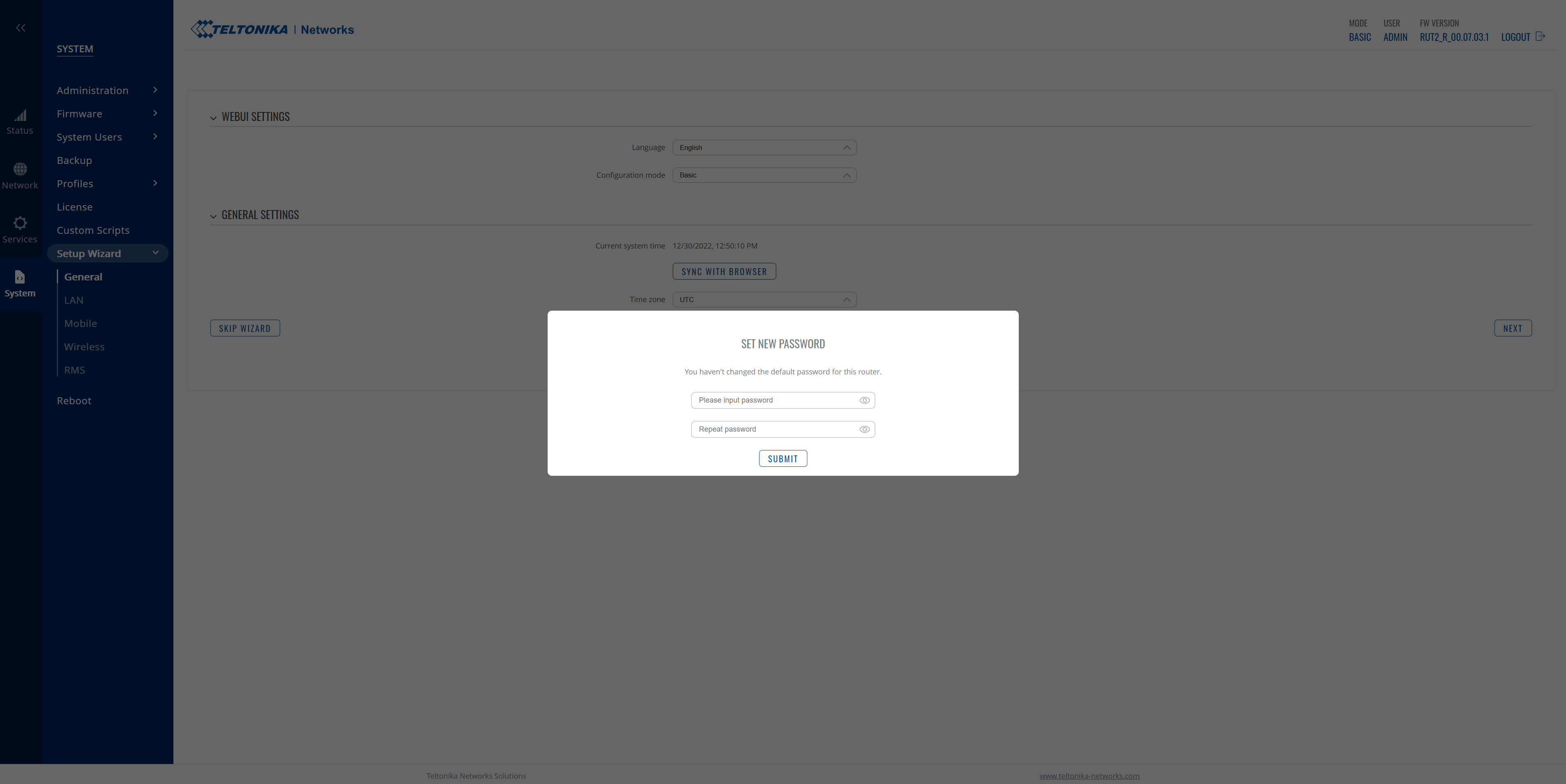
Quick Router Setup
Teltonika Networks Remote Management System is an all-in-one IoT platform allowing remote access and management of all connected Teltonika Networks and third-party devices.
We recommend that you go through this quick setup guide to activate it and enable remote troubleshooting and access.
- Set the language and date&time
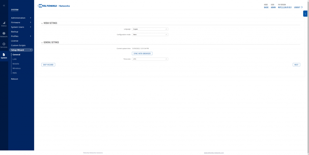
- Set the LAN configuration (for the standard application, no additional configuration is needed in this step)

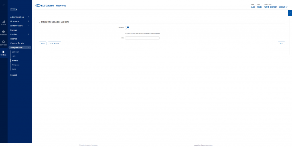
- Configure the SIM card, and introduce the SIM PIN if requested
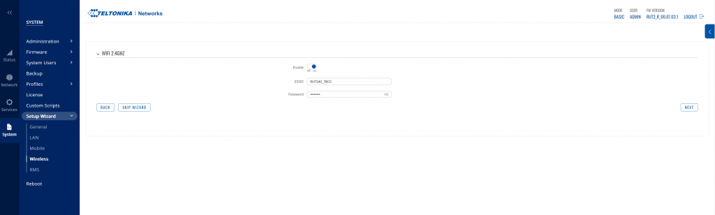
- Define a new SSID and password for the Wi-Fi if needed
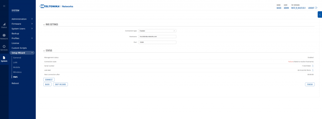
- Lastly, configure your RMS settings and validate
6. Additional configuration
The following configurations are recommended actions for using the router with Wallbox chargers and general good practices to follow.
FW update
Please make sure the router is updated to firmware version TRB1_R_00.07.01.4 or newer. The update can be done locally or through the server following this path: System > Firmware > Update. Alternatively, visit this link to download the latest firmware version and install it manually.
APN configuration
When a custom APN is required, go to Network > Interface and click “Edit” (pencil icon) MOB1S1A1.
Deactivate the Auto APN feature and set your custom APN.
Rebind protection
OCPP backends could not be reachable when there is a private APN. To make it accessible, go to Network > DNS and deactivate the “Rebind protection” feature.
Auto reboot
To prevent the router from being disconnected from the Internet and not reconnecting, go to Services > Auto-reboot > Reboot Scheduler and set a periodical auto-reboot.
Backup and restore
To create or restore a backup file, go to System > Backup and use the Backup and Restore configuration tools.
7. Status and troubleshooting
Once you finished the above steps and configured the router properly, access the Overview page:
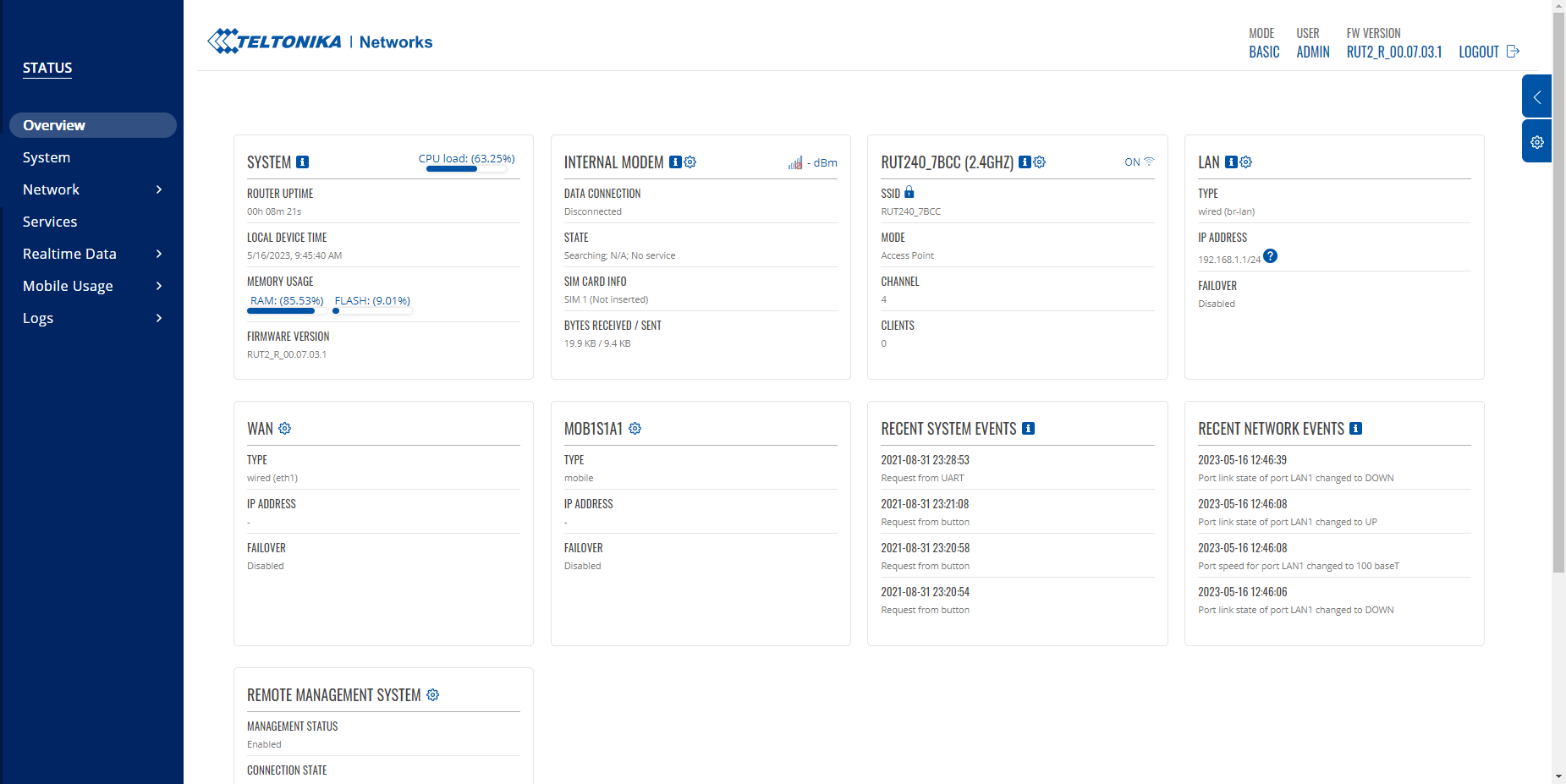
In the “Internal Modem” section, verify the following status appear:
- Data connection: “Connected”
- State: it should switch from “Searching…” to “Connected” once the communication is established
If one of the above state displays an error, check the following:
- Go to Network → Mobile and ensure the PIN introduced is valid.
- Contact your network provider to check that the SIM has been activated and is operational.